Topological approach to the assessment
of electromagnetic asymmetry of the MHD machine
Tyapin A.A.
Postgraduate student, Siberian Federal University,
Svobodny prospect, 79, Krasnoyarsk, Russia, 660041
Kinev E.S.
Сandidate of technical sciences, Director Thermal Electric Systems LLC,
Chernyshevsky St., 104, off. 85, Krasnoyarsk, Russia, 660043
Abstract. The approach to the analysis of electromagnetic asymmetry of multiphase induction MHD machines designed for stirring aluminum melt in furnaces is considered. Technological equipment for stirring aluminum is created taking into account the modes of the power supply system, ensuring the specified character of the electromagnetic field of linear induction machines. The use of high-power transistor frequency converters ensures acceptable reliability and flexibility of the power supply system. The shortened three-phase MHD machines of the longitudinal magnetic field are characterized by the presence of an open magnetic circuit, therefore, the low-frequency inverter mode turns out to be asymmetric. When designing inductors, it is important at the initial stage to evaluate the distribution of currents and the nature of the interaction of the windings, taking into account the transfer of power between the phases. For the most common three-zone and four-zone inductors, the asymmetry of the currents in the windings can be very significant. This leads to a distortion of the running magnetic mole and reduces the integral traction force of the induction machine. The evaluation of the asymmetry of the inductors of the longitudinal magnetic field for different winding switching circuits can be performed using topological equations.
Keywords: Asymmetry of the three-phase MHD machine, electromagnetic inductor, running magnetic field, electromagnetic stirrer, power supply system, symmetric component method, negative-sequence replacement circuit, frequency inverter.
Топологический подход к оценке
электромагнитной несимметрии МГД-машины
Тяпин Aлексей Андреевич
Аспирант, ФГАОУ ВО Сибирский Федеральный Университет,
Свободный проспект, 79, Красноярск, Россия, 660041
Кинев Евгений Сергеевич
К.т.н., директор ООО Тепловые электрические системы
Чернышевского, 104, офис 85, Красноярск, Россия, 660043
Аннотация. Рассмотрен подход к анализу электромагнитной несимметрии многофазных индукционных МГД-машин, предназначенных для перемешивания расплава алюминия в печах. Технологическое оборудование для перемешивания алюминия создают с учетом и режимов системы электроснабжения, обеспечивающей заданный характер электромагнитного поля линейных индукционных машин. Приемлемую надежность и гибкость системы электропитания обеспечивает использование мощных транзисторных частотных преобразователей. Для укороченных трёхфазных МГД-машин продольного магнитного поля характерно наличие разомкнутого магнитопровода, поэтому режим низкочастотного инвертора оказывается несимметричным. При разработке индукторов важно уже на первоначальном этапе оценить распределение токов и характер взаимодействия обмоток, с учетом переноса мощности между фазами. Для наиболее распространённых трёхзонных и четырёхзонных индукторов несиммметрия токов в обмотках может оказаться весьма существенной. Это приводит к искажению бегущего магнитного моля и снижает интегральное тяговое усилие индукционной машины. Оценку несимметрии режима индукторов продольного магнитного поля для разных схем включения обмоток можно выполнять с применением топологических уравнений.
Ключевые слова: Несимметрия трёхфазной МГД-машины, электромагнитный индуктор, бегущее магнитное поле, электромагнитный перемешиватель, система электроснабжения, метод симметричных составляющих, схема замещения обратной последовательности, частотный инвертор.
Formulation of the problem. In the power supply system of linear induction machines for stirring molten aluminum, low-frequency multiphase converters with a modified sinusoidal voltage are used. Transistor converters PWM for electromagnetic stirrers [1, p. 65] operate at voltages up to 1000 V at a power of less than 1000 kVA. The currents of a multiphase frequency converter 250-400 amperes are asymmetric and reactive in nature [2]. To create a running magnetic field in a melt, short-pole two-three-phase linear asynchronous motors with an open magnetic core are used [3]. The peculiarity of such machines is their small polarity under the condition 2p ≤ 2. Preliminary calculation of the electromagnetic mode of short-polar induction machines is performed approximately, according to engineering methods, and then perform numerical simulation on a computer. Often the results of numerical simulation are significantly different from the parameters laid down in the design. This is especially true for the sharp asymmetry of the currents in the phases, which leads to a shift in the magnetic poles of the inductor of the longitudinal magnetic field and to a deterioration of the traction characteristics [4]. The application of the method of symmetric components makes it possible to estimate the nature of the asymmetry of the currents of the induction machine and to propose measures for correcting the regime.
The specificity of the design of short-pole induction machines determines the asymmetric mode of the inductor power supply system [5]. When designing induction machines, it is difficult to fully estimate the distribution of currents, taking into account the mutual inductance of the phases and the transfer of power between closely spaced windings of the inductor [6]. In addition, when developing a frequency converter for an induction machine, during the construction of a transistor inverter and creating control algorithms for a power module, it is necessary to provide all possible modes of operation [2].
Solution. For stirring aluminum melt to using inductors of a longitudinal or transverse magnetic field. The indicated magnetohydrodynamic (MHD) devices are distinguished by different efficiency and cost [7]. For small-capacity furnaces, it is advantageous to use shortened inductors of a longitudinal running field, which are distinguished by simplicity and low cost. In the composition of each MHD stirrer, in addition to the inductor, a low-frequency multi-phase converter is used [8]. For induction MHD machines of three-, four- and six-zonal construction, three-phase inverters are used.
The most significant mode feature of the power system of the inductor of a longitudinal magnetic field can be considered a radical change in the phase relationships between voltages and currents in the phases of the inverter [9]. Inverse inclusion of the induction machine windings [10], current asymmetry, power transfer between the windings, can lead not only to a change in the reactivity character from the inductive to the capacitive, but also to the mutation of the mode at which the inverter becomes an electric receiver. This phenomenon is preferably investigated at the stage of analysis of the circuit configuration of the «inductor-inverter» module [11]. This allows us to estimate the limits of the change in the performance characteristics and formulate the requirements for the construction of an algorithm for the operation of electronic components in the control system for pulsed power switches [12]. The fact is that the currents of the steady-state regime of different phases can differ by a factor of two, so the maximum permissible operating parameters of IGBT-transistors, especially taking into account impulse overloads, should be chosen reasonably [8].
In the algorithm of the PWM controller, states should be provided in which the instantaneous current in the inductor winding is in antiphase with the voltage of the half bridge module for a long time. In the power supply system of the induction machine, large reactive powers circulate, since the inductor mode is close to idling. The lack of rotation in induction machines also creates the features of electronic control during an emergency stop [12]. The algorithm for controlling electronic units provides for an instantaneous reset of reactive power to the ballast in emergency shutdown mode.
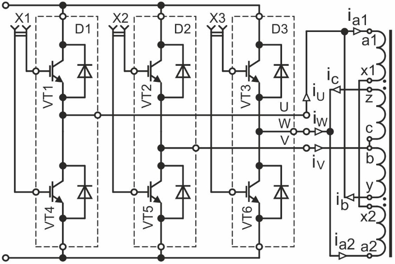
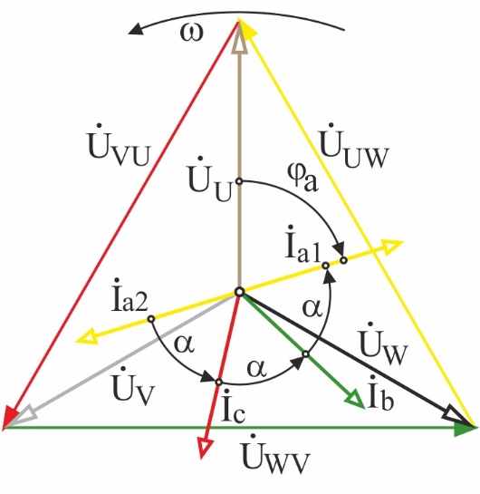
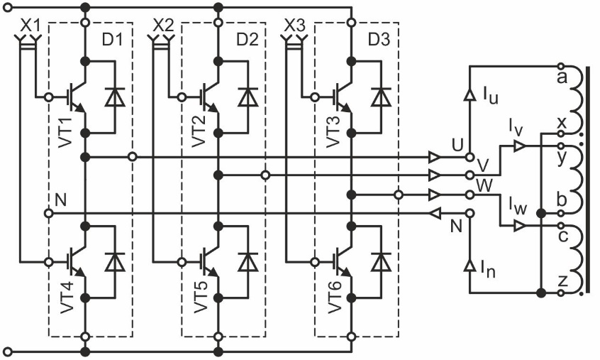
The circuit of the power module of the frequency inverter based on three half-bridges (D1, D2, D3) is shown in Fig. 1, a. The scheme provides for the inclusion of a three-phase four-zone inductor according to the scheme with parameters m = 3, 2p = 4/3, Z = 4, α = 60; according to figure 2. The advantage of this configuration of the induction machine is a longer segment of the circle and an enlarged arc sector within which magnetic fluxes are created that create traction. As can be seen from the vector diagram shown in Fig. 1, b, the effective pulling force creates fluxes in the raster π/2, which is half the circumference.
 |
 |
| a | b |
| Figure 1 | |
Judging by the vector diagram (Fig. 1, b), it is easy to confirm that the phase shift of the magnetic makes an angle α = π/6, which is more advantageous to have within such a small pole division. At the same time, an inductor with such a connection scheme becomes a four-zone one and can turn out to be somewhat larger, which should be constructively limited in the design.
 |
| Figure 2 |
The next step should be to highlight the features of connecting the induction machine to the frequency converter and formulate the basic requirements for the power supply mode of the windings. First of all, this refers to the ratio of the phase angles of the currents, which provide a given alternation of the poles of the magnetic field. To estimate the nature of the distribution of currents in the linear wires of the power supply, one can write down a system of equations according to Kirchhoff’s laws. At the initial stage, taking into account the open nature of the magnetic circuit, the magnetic bonds between the phases should be neglected

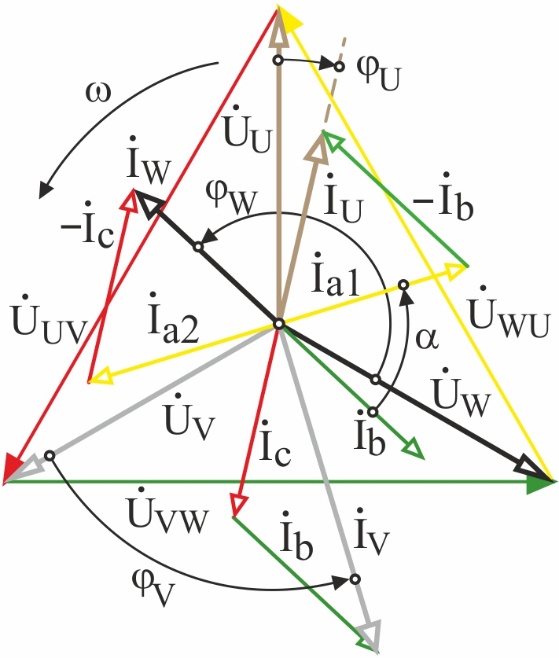
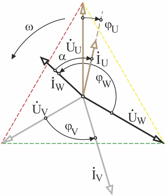
According to the system of equations (1) for the steady-state regimes of a three-phase inductor of a longitudinal magnetic field, a vector current diagram is constructed in Fig. 3, a. An approximate solution is performed for the first harmonic, without taking into account the saturation of the steel, when connecting the windings of a linear induction machine in the reverse order of the phase sequence. The resulting current distribution indicates an extremely significant asymmetry of the three-phase inverter mode. Judging by the vector diagram, the sum of the currents of the first and third phases IU and IW is equal to the current of the second phase IV, provided that the phase angles α ≈ 2/3 are approximately equal.
Thus, in a simple example of analysis, important information can be obtained for the design of a frequency converter, the power link of which must allow continuous operation with asymmetry of this kind, and the electronic components must be rated for electrical overload at 1.73 times the nominal value. In this case, the inverter protection system must understand the asymmetric current distribution in the adaptive mode. Even more important is the recognition of the asymmetry of the currents of the frequency converter taking into account the magnetic bonds between the windings of the inductor and the saturation of the steel.
 |
 |
| a | b |
| Figure 3 | |
It can be noticed, however, that in this case, the open configuration of the magnetic circuit largely attenuates the distortion of the currents [4]. Nevertheless, the close arrangement of the windings of neighboring phases, within one pole division, can further aggravate the asymmetry of the currents within the range of 25-30 %.
From the vector diagram of voltages and currents, it is possible to estimate the presence of power transfer between adjacent phases, for this it is necessary to represent the same-named quantities on the complex plane and indicate the corresponding phase angles between currents and voltages, as shown in Fig. 3, b. Judging by the nature of the angles, it can be concluded that only in the first phase the current lags behind the voltage by the angle φV, which corresponds to the inductive nature of the load, and the phase of the inverter retains the status of the generator. In phase V, the angle between the current and voltage φW only slightly does not reach 90°, and the current is ahead of the voltage, which indicates the capacitive nature of the load. As for the third phase, the voltage and current are fixed in the mode close to antiphase. In this case, the phase shift φU only slightly does not reach the value of π, which indicates the transfer of power, and the phase of the inverter acquired the character of an electrical receiver. The obtained results should be considered when building control algorithms for pulsed power switches of a low-frequency inverter.
Asymmetric phase modes in power supply systems of electrical installations are often investigated using the method of symmetric components. For example, in currents of an induction machine of a longitudinal magnetic field, for different schemes of winding inclusion, it is possible to calculate the components of direct, reciprocal and zero sequence

The resulting currents in the phases of the transistor inverter are determined by mutual relations, which are used to estimate the regime in the set of complex circuits for replacing the power supply system of the induction machine

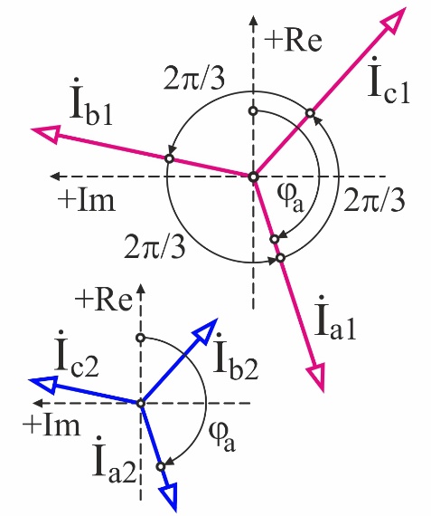
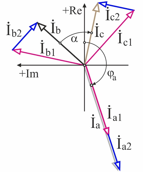
Taking into account the nature of the asymmetry of the currents, we can apply the method of symmetric components to the three-phase system of vectors and obtain the corresponding schemes for substituting the direct and reverse sequences. It should be noted that, since the inclusion of the windings of the induction machine shown in the diagram (Fig. 1, a), even during splitting, keeps the connection in a triangle, there will be no zero sequence components in the currents. And this simplifies the construction of an equivalent vector diagram. When choosing a coordinate system for the symmetric component method, you can to bind the phase voltage vector UV to zero. Then the idealized system of asymmetric current vectors (Fig. 4, a) can be represented in the following form:

By the formulas of symmetrical components, the values of the currents of the direct and reverse sequence can be calculated (Fig. 4, a), provided . It should be noted that for the reverse sequence a significant current is calculated, equal to half the current of the direct sequence I2 = I1/2.
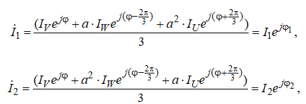
This confirms the high degree of distortion of the symmetry of the system of currents, as shown in Figure 4. Since it was possible to calculate the symmetrical components of the currents for the inductors of the longitudinal field, it is then easy to proceed to the construction of replacement schemes for the induction machine for the forward and reverse sequences. At the same time, in analyzing the regime of the power supply system, one can traditionally leave from the study of an asymmetric regime and calculate both for a symmetric state.
However, this calculation should be regarded as approximate, since the saturation of the steel of the magnetic circuit was not initially taken into account. Nevertheless, with the application of such an approach, it is not at all difficult to obtain an idea of the nature of the currents in the phases. And already at the next stage of calculation it is possible to pass to the estimation of the regime parameters taking into account the saturation of the core. Moreover, based on the results of the calculation, for example, using the harmonic balance method and subsequent spectral analysis, the odd harmonics of currents and voltages can also be grouped by indices and correlated with a direct or reverse sequence. This will cause the vector diagrams of the symmetrical components to be corrected and to obtain refined values of the currents and voltages of the inverter.
 |
 |
| a | b |
| Figure 4 | |
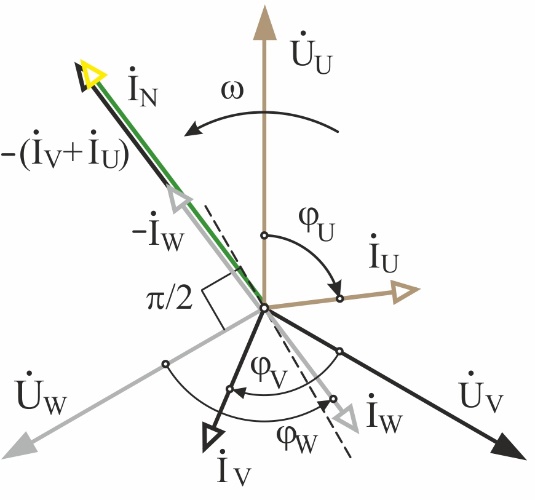
It is noteworthy that for the classical layout of a three-zone induction machine (Figure 5, a) and the inclusion of windings with a star with an inversion of the middle phase, by analogy with a triangle, the symmetric component method can also be applied. Given the phase angles, the currents in the side phases remain inductive, since the phase angles φU > 0 and φV > 0. And since the current of the inverted mean phase (φW < 0) outstrips the voltage by an angle greater than π/2, then two consequences arise. First, the reactivity of the medium phase current acquires a capacitive character, and secondly, the nature of the generation changes. According to the vector diagram, the inversion of the current of the middle phase leads to a power transfer, and the third phase of the inverter essentially becomes an electric receiver.
 |
 |
| a | b |
| Figure 5 | |
It is noteworthy that the current in the neutral of a linear induction machine is equal to twice the nominal phase current of the inverter, and the modules of currents in the phases of the induction machine are equal to each other. Taking into account the magnetic connection between the windings, the vector diagram will be significantly distorted, which should be taken into account when selecting components. To the idealized distribution of currents shown in the diagram, we also apply the method of symmetric components. To obtain symmetrical components, the phase currents should be written in complex form and the system of equations (2) applied. You can perform calculations manually or use a computing environment, such as Mathcad.
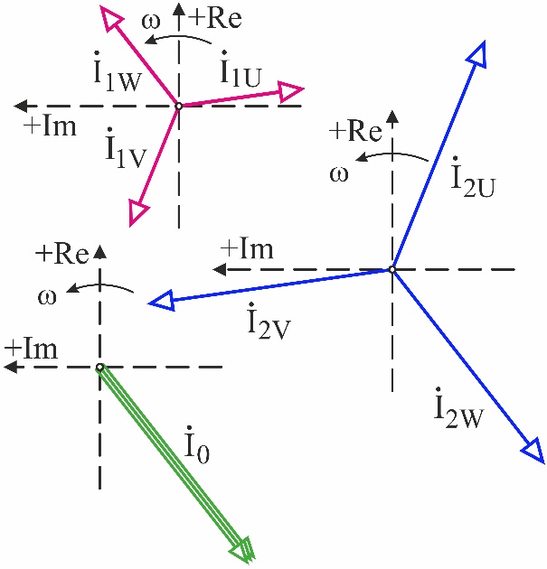
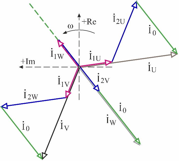
The symmetrical current components calculated from expressions (2) are shown in Fig. 6, a. The modules of currents of the reverse and zero sequences are equal to each other and three times higher than the current of the direct sequence I0 = I2 = 3 I1. The proportions of the module of the symmetrical components reflect such a sharp character of the asymmetry. Using the calculated vectors, expression (3) creates an equivalent vector diagram, as shown in Fig. 6, b. The current of each phase is determined by analytical or graphical summation of the symmetric components using the rotation operator a.
 |
 |
| a | b |
| Figure 6 | |
It is noteworthy that from the values of the symmetric components it is easy to understand that the current in the neutral wire can be considered as a set of zero-sequence currents of all phases. In addition to the vector diagram shown in Fig. 6, b, according to Kirchhoff’s law, it is possible to obtain the current vector in the inductor neutral as the sum of the currents of all phases. The specific characteristics of the device in question as a complex for stirring a melt containing a multiphase induction machine and a multiphase inverter allow us to use, in addition to traditional methods of analysis, modern computational tools oriented to the application of algorithms of applied mathematics. To calculate the electromagnetic modes of asymmetrical three-phase systems, it is often more convenient to use specialized software, for example, Ansys Multiphysics [9].
However, the construction of a full-scale model of the EMS complex does not exclude a preliminary analysis of the power supply mode according to the scheme for including the inductors of the longitudinal magnetic field. Good results of the analysis of the traveling magnetic field distribution are provided by the CFX and Fluent subsystem, which allows not only to simulate the power supply system, but also a low-pole induction machine with aluminum melt in a full-phase representation [10]. It is at the modeling stage that the solution of the problem of accounting for asymmetric modes in the power supply system is achieved. To do this, the parameters of the model specify not only the nature of the currents, but also the parameters of the mutual inductance. They are determined through the coupling coefficient of the coils of the inductor of the longitudinal magnetic field. In addition, when constructing a numerical model, the nonlinear character of inductive coupling is taken into account. To do this, the real magnetic characteristics of the steel core are determined and the degree of saturation of the teeth and magnetic circuit in the steady state.
It should be noted that the interface of the software environment Ansys allows you to create mathematical models of enormous size, consisting of modules that work in different subsystems. In this case, it is far from always rational to create hybrid models that take into account the features of the temperature and magnetic fields of the inductor in conjunction with the electromagnetic regimes of the power supply system. In most cases, the calculation and simulation of the regime of the power supply system can be separated from the simulation of the electromagnetic mode of the inductor. But at the same time, it is always necessary to introduce the corresponding boundary conditions, allowing to combine the results obtained at the borders of the regions, based on the parameters of the nominal power supply mode.
Conclusions. Induction MHD machines of a longitudinal magnetic field, intended for stirring melts, are distinguished by the asymmetry of the electromagnetic mode. To correct the distribution of currents that create a traveling magnetic field, a preliminary analysis is applied using topological equations and the subsequent regulation of the linear current load of the inductor. The required value of the magnetizing force of windings of each phase is clarified by the adjustment characteristics at the stage of modeling the electromagnetic field and power circuits of the MHD machine. In addition, software-algorithmic regulation of the amplitude-phase operating parameters of the inverter is used to adjust the characteristics of the induction MHD machine, which allows aligning the distribution of traction in the melt. With any distribution of currents in the windings, the use of analysis of the regimes by topological equations allows us to formulate a set of requirements for developing algorithms for controlling the power switches of frequency converters and building a special series of metallurgical inverters. Among the requirements can be identified greater resistance to overload with an extremely low power factor and immunity to asymmetry in phases when working on the edge of the frequency range.
References
1. Tyapin, A. A. Inductors for electromagnetic stirrers // Znanstvena Misel Journal / Global Science Center LP, Lubljana, №19-1, 2018. – p. 64-67.
2. Tyapin, A. A. The structure of electromagnetic stirrers // Znanstvena Misel Journal / Global Science Center LP, Lubljana, №20-1, 2018. – p. 50-57.
3. Vol’dek, A. I. Indukcionnye MGD-mashiny s zhidkometallicheskim rabochim telom. – L.: EHnergiya, 1970. – 272s.
4. Vol’dek, A. I. Iskazhenie simmetrii napryazhenij i tokov v indukcionnyh mashinah s razomknutym magnitoprovodom. Izvestiya vuzov, Elektromekhanika, 1960. № 5. – s. 78.
5. Mishchenko, V. D. Tekhnologiya ehlektromagnitnogo transportirovaniya legkih splavov / V. D. Mishchenko, A. EH. Mikel’son, YU. K. Krumin’. – M.: Metallurgiya, 1980. – 128 s.
6. Krumin’, YU. K. Osnovy teorii i rascheta ustrojstv s begushchim magnitnym polem. – Riga: Zinatne, 1983. – 278 s.
7. Baranov, G. A. Raschet i proektirovanie indukcionnyh MGD-mashin s zhidkometallicheskim rabochim telom / G. A. Baranov, V. A. Gluhih i dr. – M.: Atomizdat, 1978. –248s.
8. Golovenko, E. A. Tekhnologiya ehlektromagnitnogo vozdejstviya na rasplav alyuminiya v mikserah i pechah / E. A. Golovenko, V. A. Goremykin, E. S. Kinev i dr. // Cvetnye metally. – 2014. № 2 (854). S. 86-92.
9. Tyapin, A. A. Ocenka glubiny proniknoveniya ehlektromagnitnoj volny v rasplavlennyj alyuminij / Innovacionnye nauchnye issledovaniya: teoriya, metodologiya, praktika: sbornik statej XV Mezhdunarodnoj nauchno-prakticheskoj konferencii // A. A. Tyapin, V. YU. Andryushchenko, V. A. Goremykin, E. S. Kinev. – Penza: MCNS «Nauka i Prosveshchenie». – 2018. S. 27-34.
10. Tyapin, A. A. Gidrodinamika raspredelennogo polya skorostej rasplava alyuminiya / A. A. Tyapin, V. YU. Andryushchenko, V. A. Goremykin // Metody prognozirovaniya v tekhnike i tekhnologiyah. Sbornik statej po itogam Mezhdunarodnoj nauchno-prakticheskoj konferencii (Perm’, 28 sentyabrya 2018). – Sterlitamak: AMI, 2018. – S. 75-85.
11. Mycyk, G. S. Trekhfaznye invertory napryazheniya, nechuvstvitel’nye k nesimmetrii nagruzki / G. S. Mycyk, Hlaing Min U. – M.: Vestnik MEI. № 4. 2016. – s.62-68.
12. P’yu M’int Thejn. Sozdanie informacionno-metodicheskogo obespecheniya dlya sistemnogo proektirovaniya staticheskih preobrazovatelej chastoty v sostave mashinno-ehlektronnyh generiruyushchih sistem dlya maloj ehnergetiki i avtonomnyh ob»ektov: Avtoref. dis. … k.t.n. M.: NIU «MEI», 2013. – 20 s.
Список использованных источников
1. Tyapin, A.A. Inductors for electromagnetic stirrers // Znanstvena Misel Journal / Global Science Center LP, Lubljana, №19-1, 2018. – p. 64-67.
2. Tyapin, A.A. The structure of electromagnetic stirrers // Znanstvena Misel Journal / Global Science Center LP, Lubljana, №20-1, 2018. – p. 50-57.
3. Вольдек, А.И. Индукционные МГД-машины с жидкометаллическим рабочим телом. – Л.: Энергия, 1970. – 272с.
4. Вольдек, А.И. Искажение симметрии напряжений и токов в индукционных машинах с разомкнутым магнитопроводом. Известия вузов, Электромеханика, 1960. № 5. – с. 78.
5. Мищенко, В. Д. Технология электромагнитного транспортирования легких сплавов / В. Д. Мищенко, А. Э. Микельсон, Ю. К. Круминь. – М.: Металлургия, 1980. – 128 с.
6. Круминь, Ю. К. Основы теории и расчета устройств с бегущим магнитным полем. – Рига: Зинатне, 1983. – 278 с.
7. Баранов, Г. А. Расчет и проектирование индукционных МГД-машин с жидкометаллическим рабочим телом / Г. А. Баранов, В. А. Глухих и др. – М.: Атомиздат, 1978. –248с.
8. Головенко, Е. А. Технология электромагнитного воздействия на расплав алюминия в миксерах и печах / Е. А. Головенко, В. А. Горемыкин, Е. С. Кинев и др. // Цветные металлы. – 2014. № 2 (854). С. 86-92.
9. Тяпин, А. А. Оценка глубины проникновения электромагнитной волны в расплавленный алюминий / Инновационные научные исследования: теория, методология, практика: сборник статей XV Международной научно-практической конференции // А. А. Тяпин, В. Ю. Андрющенко, В. А. Горемыкин, Е. С. Кинев. – Пенза: МЦНС «Наука и Просвещение». – 2018. С. 27-34.
10. Тяпин, А. А. Гидродинамика распределенного поля скоростей расплава алюминия / А. А. Тяпин, В. Ю. Андрющенко, В. А. Горемыкин // Методы прогнозирования в технике и технологиях. Сборник статей по итогам Международной научно-практической конференции (Пермь, 28 сентября 2018). – Стерлитамак: АМИ, 2018. – С. 75-85.
11. Мыцык, Г. С. Трехфазные инверторы напряжения, нечувствительные к несимметрии нагрузки / Г. С. Мыцык, Хлаинг Мин У. – М.: Вестник МЭИ. № 4. 2016. – с.62-68.
12. Пью Мьинт Тхейн. Создание информационно-методического обеспечения для системного проектирования статических преобразователей частоты в составе машинно-электронных генерирующих систем для малой энергетики и автономных объектов: Автореф. дис. … к.т.н. М.: НИУ «МЭИ», 2013. – 20 с.


